
Danger spotted, danger averted – Safety solutions to prevent unexpected start-up

Companies repeatedly have to contend with serious, even fatal, accidents caused by the unexpected or unseen start-up of complex machinery and systems.
Risks due to the unexpected start-up or restart of hazardous movements exist in accessible machinery areas or if protective devices can be can be bypassed and people are present in those areas without being noticed – perhaps on account of maintenance or repair work. These risks need to be determined as part of a risk assessment, which every machinery manufacturer or system integrator must carry out and document under the Machinery Directive.
The particular problems that this topic presents were the reason for a dedicated harmonised standard EN 1037 ‘Prevention of unexpected start-up’, the successor standard to which has been published as EN ISO 14118:2018.
EN ISO 14118:2018: Prevention of unexpected start-up
The standard offers an overview of a range of aspects and requirements that must be considered. In addition, it also lays down design safety measures that seek to prevent unexpected start-up in order to allow safe intervention by people in hazardous areas.
The standard refers to unexpected start-up due to all types of energy, i.e. energy supply (electrical, hydraulic, pneumatic), stored energy (gravity, tensioned springs), which is often overlooked, and other external influences (wind).
The following presents some example safety solutions on the topic, all of which are available in the range provided by Schmersal.
Versions of the stop command
In the following, it is assumed that a stop command is safely generated by a protective device being triggered in the input, logic and output chain with the necessary performance level and is executed in the form of a stop of category 0, 1 or 2.
The standard EN 60204-1 outlines the different categories according to which a stop command, depending on the best possible hazard reduction, can be executed
- as an uncontrolled shutdown (by immediately interrupting the energy supply: stop 0) or
- as a controlled shutdown (by time-delayed interruption of the energy supply: stop 1).
Safety-related standstill monitoring is also required (see also EN ISO 14118:2018), if a stop command is executed as a stop of category 2, i.e. as a similarly controlled shutdown, but here the energy supply is maintained, even at standstill.
All Schmersal protective devices and safety-related control devices offer a wide range of options for the accomplishment of safety-related stop commands. Safety relay modules in the SRB-E series are especially suitable for stop category 0, for example.
Permanent stop command
A permanent stop command has a particular role to play when a person is required to work for an extended period of time in a hazardous area with blind spots.
In this context, ‘permanent’ means that no third person can initiate or cause the machine to start. A hazardous area can easily have many blind spots for third persons consider linked individual machines, integrated production systems and machinery plants.
A simple yet more effective means of achieving this objective is to use lockout tags for movable guards (guard doors, safety grids, etc.). These accessories make it possible to secure interlocking devices (safety switches with and without interlock) in the open state by means of padlocks such that it is not possible to actuate the devices again. This effectively prevents reclosure of the movable guard and restart of a machine by a third person – both mechanically and in terms of control technology.
One design example is the AZM400 electronic solenoid interlock with lockout tag.
Key transfer systems also offer smart options for protection against an unexpected (unintentional) start-up, particularly when operators are working in a complex hazardous area or need to use special modes of operation.
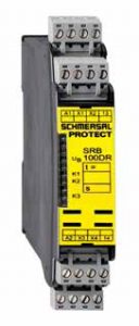
The safety relay module
PROTECT SRB 100DR
can be used for the double
acknowledgement function
Single and double acknowledgement systems
Such additional measures are not necessary in all cases. Also, not always are interlocking movable guards necessary that are safeguarded with interlocking devices. For example, sometimes it is better to use optoelectronics.
For other applications in complex hazardous areas, acknowledgement systems may be considered, whereby a distinction is made between single and double acknowledgement
A single-acknowledgement system comprises an acknowledgement button fitted outside of the hazardous area, which cannot be actuated from inside the accessible area without triggering the protective function. The acknowledgement button must be positioned such that there is a clear view of the hazardous area.
The restart of hazardous movements must only be possible:
- After actuating the acknowledgement button following an interruption of the light curtain, or
- After closure of the respective movable guard, followed by actuation of the acknowledgement button (source: Employer’s Liability Insurance Association for Raw Materials and the Chemicals Industry BG RCI, Sheet T 008).
The double acknowledgement procedure is explained here using the example of Schmersal’s PROTECT SRB 100DR relay module. The function of the module ensures that the machine controller can only be switched on again if
- The operator firstly actuates a reset or restart button 1 located within the system and, after leaving the hazardous area, if applicable, closes and locks again a separating safety device Especially for the stop category 0 the safety relay modules of the SRB-E series can be used.
- a reset or restart button 2, which is fitted outside, was subsequently actuated. A time window (adjustable via DIP switch) of 3 to 30 seconds is provided for execution of ‘double’ acknowledgement in which the actuation in the sequence button 1 then button 2 – must take place. The time window can be oriented to the operational processes.
If the operator fails to press first button 1 or does not press button 2 within the time window, there is no release and the double acknowledgement process must be repeated. Further signal processing of the reset signal is then carried out via commercially available safety relay modules, such as the PROTECT- SRB series, i.e. the SRB 100DR module is a ballast unit with performance level ‘e’.

Signal processing of the falling or rising edge on reset buttons?
Whether a reset signal (synonymous with restart, acknowledgement or reset signal) is executed as a single or double after leaving a hazardous area, the same question arises: With electrotechnical setups, is the evaluation of the reset signal only permissible via the falling edge or via a rising edge as well?
After carrying out an FMEA (Failure Mode Effect Analysis), the DGUV‘s, Wood and Metal Department, has concluded that ‘both variants function safely due to the edge evaluation when an error occurs. Not all errors are, however, recognised immediately in both solutions. This can lead to a false positive if another error then occurs. Decisive for the realisation of a reset signal is not the type of edge detection (high-low or low-high), but correct evaluation of the dynamic behaviour as well as the requisite error detection in the evaluation device. Even with a rising reset signal edge, the requirements in accordance with DIN EN ISO 13849-1 can be satisfied accordingly if implemented correctly.’ (Source: DGUV-Information, ‘Manual reset device for the reset function in accordance with DIN EN ISO 13849-1’, edition 02-2015).
In addition, the following also applies to the reset function:
- It must be provided by a separate, manually operated device in the safety-related part of the machine control system, and
- The device may only be accessed if all safety functions and protective devices are functional;
- It must not itself initiate any movement or hazardous situation and the reset function is an intended action that enables the controller to accept a separate start command.
The performance level must not diminish the safety of the associated safety function. Further requirements on the topic of resetting can be found in DIN EN ISO 13849-1, Section 5.2.2.
![]()