
Application Engineer |
Rishabh Instruments Pvt. Ltd
When the load on a system exceeds the amount of power that a single or existing number of generators can deliver, an additional generator is connected to the system to deliver required power. This method of adding an alternator in the existing system is called ‘parallel operation of alternators’. It is essential to know that the incoming alternator must be paralleled such that each machine is supplying a proportionate amount of active and reactive power to the common load. For which certain rules are to be kept in mind.
Necessary conditions for parallel operation:
It is never recommended to connect an alternator at standstill i.e stationary alternator to bus-bar of a live system. An alternator at standstill generates no stator e.m.f which when connected with a rotating alternator would act as a load instead and cause internal circulating currents, which can lead to major faults.
There are certain requirements which must be fulfilled before an incoming alternator can be put in parallel with the with the existing alternator, this is called synchronizing.
And the conditions to be taken into consideration while synchronizing are as follows:
- The voltage of the incoming alternator must be same as the bus-bar voltage.
- The frequency of the incoming alternator must be same as the frequency of bus-bar voltage.
- The phase of incoming alternator voltage must be identical to the phase angle of bus-bar voltage.
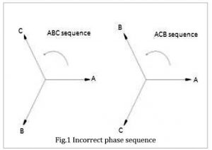
- The phase sequence must be identical, in case of a three-phase alternator.
What happens when the parameters are not matched?
Alternator voltage:
The magnitude of internal voltages of both incoming and existing alternator must be identical else a potential difference will be created, causing circulation of currents amongst the the two alternators and this is undesirable.
Voltage phase shift:
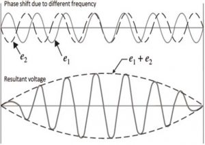
When the zero crossing of both the voltage wave forms are not the same, a phase shift occurs resulting into voltage whose magnitude keeps on changing. This can be explained as a voltage which when given across a lamp will make it illuminate with different intensities.
Alternator speed:
Suppose, the magnitude of alternator voltage of both the existing unit and incoming unit are same (depending upon the field excitation) and in-phase to external local circuit named e1 and e2. In this case even though the voltages are same but if speed of the alternator are not equal i.e. Ns1 Ns2 ,the frequencies of both the alternators will not match resulting into a phase shift between the two voltages. The waveform obtained is as shown below.
It would then be similar to the second case i.e phase shift leading to constantly varying resultant voltage
Incorrect phase sequence :
Incorrect phase sequence will cause damage, the bigger the phase difference the more electro-mechanical force is between the two out-of-phase alternators.
Synchronizing:
The method by which alternators are operated in parallel such that the above specified conditions are met is called synchronizing.
To ensure that the alternators are well synchronized, several methods are used and are listed below;
i. Three lamp dark method
ii. Two lamp bright method
iii. Using Synchroscope
The first two methods use a combination of connections to ensure that the alternator voltage has similar magnitude, phase sequence, frequency and zero phase shift with the bus-bar voltage.
- The lamps illuminate with different intensities when there is a deviation in any of the quantity mentioned above.
- Lamps dark out and glow alternatively.
- In case of dark lamp method, when lamps go dark the alternators are synchronized as it indicated that the voltages e1 and e2 are in direct phase opposition leading to no circulating current.
- Whereas, in lamp bright method the connections are made such that lamps will glow with maximum intensity when the two voltages are in-phase and resultant voltage is twice the voltage of both alternators.
- But these methods using lamps in not quite accurate and require operator’s expertise to switch alternator in at the right instant.
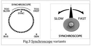
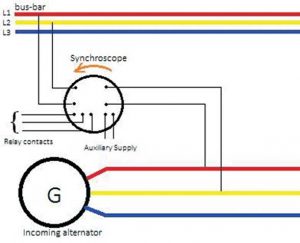
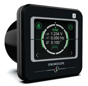
- Hence, a device called synchroscope is used which indicates deviation in voltage (ΔV), frequency (Δf) and phase shift (ɸ).
As shown in fig., a synchroscope is connected to the system and accurate instant of time is achieved at which synchronization is to be done.
Synchroscopes come in different variants, generally they are indicative type which show the speed and phase shift of the alternator either by a pointer or LEDs arranged in a circular fashion.
We introduce to you a synchroscope which has the same functionalities as that of a basic synchroscope and comes with additional features of:
- Touchscreen display
- Consumes less power
- Highly accurate
- Aesthetically appealing
- ANSI housing.


